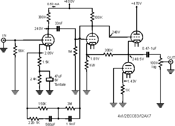
That's my preamp. I love it ... I named it "First", because it was my first project. Actually, I'll probably modify it by splitting the control buttons (source selector and volume) in a separate box, the preamplifier will be only an in-out box. Schematic by Jean Hiraga and published in L'Audiophile n° 21 (Sept. 81).

The resistor (220-1K) adjusts the response over 15kHz.
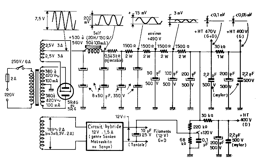
The original power supply, heavily filtered. I've increased the values of the capacitors.
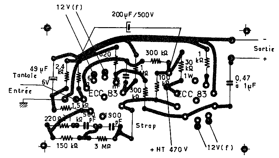
This is the original design, actually my preamp has another layout. Each printed line is doubled by a soldered wire.
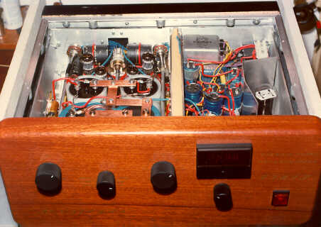
A global view from this preamplifier. It weighs about 20kg. The front plate is in wood (made by my brother). It's a three-boxes architecture. The power supply (right block) is separated from the circuits (left block). The volume buttons are independent and the display shows the final supply voltage (470V) with the relative knob to adjust it.
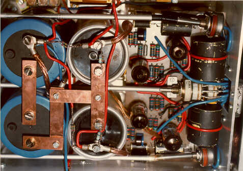
The four monsters on the left are the last supply stages. The circuit itself is on the right, you can see the four tubes E83CC, the source switch (Elma with gold-plated contacts, two circuits in //), the two potentiometers (Allen Bradley, agglomerated carbon: really, but really better than anything else I tried, just a little bit noisy) and the two large output capacitors (Polypropylenes from Leclanché, covered with a conductive paint to avoid static electricity). There is also a discharging circuit at the top (relays through power resistors) to avoid to keep high voltage to the tubes (and perhaps to the user !) when not in use.
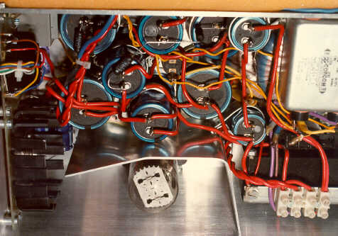
These are the first stages of the power supply, you can see (from right to left): the two toroidal transformers (high and low voltage are separate) with a filter over them, the big choke under, the valve with a protection to avoid overheating the capacitors, the capacitors battery and finally the regulated power supply for the tubes filaments and a small supply for the voltage display.