RL = input impedance of the next stage
Rk = cathode resistor
Rp = plate resistor
In the following schematics:
RL = input impedance of the next stage
Rk = cathode resistor
Rp = plate resistor
![]() = gain of the
tube
= gain of the
tube
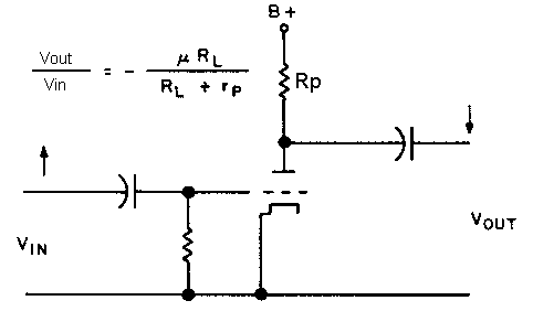
This is the most common way to use a tube. The plate is loaded with a resistor. A change of the current through that resistor gives a change in the voltage across it. The signal is inverted.

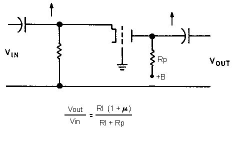
The grid is connected to the ground. Not very usual. The gain is higher than with a plate loaded. The signal is not inverted.

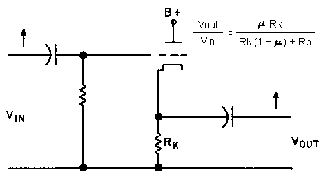
The output signal is taken from the cathode, the resistor is also connected to the cathode. It is often used for its low output impedance. The gain is inferior to 1. The signal is not inverted.

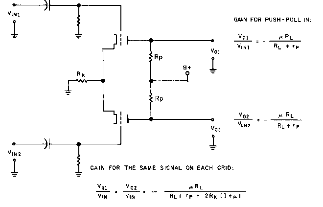
This stage is used very often on transistor schematics. It is also often used in tube schematics as a stage following the phase splitter because it increases the symmetry of the two signals before the power stage.
