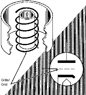
Electric charges of the same polarity repel each other thus a negative charge, with its excess of electrons, applied to the grid push back the electrons coming from the cathode.
The electronic era was starting ...
 |
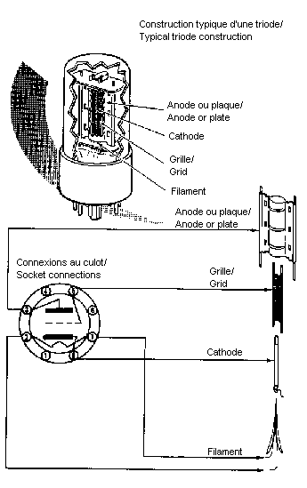
After the diode invention, Lee de Forest
had the idea to put a grid between the cathode and the
plate. By applying a variable negative voltage, he
managed to vary the current flowing through the tube. Electric charges of the same polarity repel each other thus a negative charge, with its excess of electrons, applied to the grid push back the electrons coming from the cathode. The electronic era was starting ... |
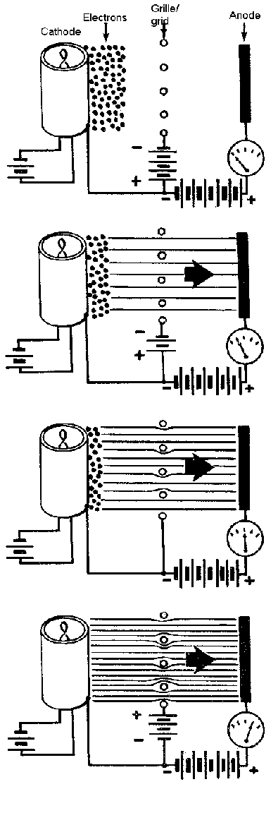 |
A highly negative grid can stop completely the current flowing in the tube. A less negative grid lets a small current flowing. A grid at the same voltage than the cathode lets a high current flowing. A positive grid not only drives the tube to saturation (the current will no more increase after a certain level) but a grid current appears also. |

the variations of the grid voltage provoques a variation in the tube and plate resistor current and thus a voltage variation at each side of this resistor (U=R.I).
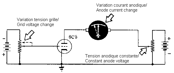
With a constant plate voltage, a variation of the grid voltage gives a variation of the plate current.

With a constant grid voltage, a variation of the plate voltage gives a variation of the plate current.
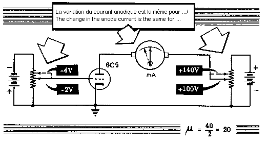
In this example, a change of 2V in the grid voltage gives the same current change as a plate change of 40V.
 |
= Ri.S |
where Up = plate voltage
Ug =
grid voltage
Ri =
internal resistance of the tube
S =
tube slope
The amplification factor of a tube is called "miu" and,
in this example, equals 20.
With a constant grid voltage.
![]()
where Up = plate voltage
Ip =
plate current
Ri =
internal resistance of the tube in Ohms
![]()
where Ri = internal resistance of the tube
Ug =
grid voltage
Ip =
plate current
S =
tube slope in A/V or mA/V
The gain of a tube stage, whatever the tube type, is computed by:
![]()
where Ri = internal resistance of the tube
Rp =
plate resistor
 |
This curve indicates the plate current variation when applying a variable grid voltage and a constant plate voltage. The linear part indicates the grid voltages where the tube could operate with low distorsion. in this example, the cut-off voltage is around -14V. Its a typical figure of an audio amp.
To obtain big variations in the plate current, it's
much more effective to apply a variable voltage to the
grid than to the plate. You can see that a lower grid voltage gives a higher plate voltage. The signal is inversed. |